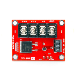
VClamp for RoboClaw or MCP Controllers
Tutti i prezzi sono IVA inclusa
The VClamp allows RoboClaw and MCP motor controllers to be used with switching power supplies by dissipating excess regenerative energy through a connected external resistor (not included). The VClamp connects directly to the motor power supply and gets logic power and signals from the RoboClaw or MCP controller. The clamping voltage is set in the Basicmicro Motion Studio software, and the board can handle peak voltages and currents up to 60 V and 60 A. A status LED lets you know when the voltage is being clamped.
Overview
Most motor controllers encounter scenarios (typically when a motor is slowing down) where energy from a motor is returned to the power supply. That power supply is commonly a battery that can tolerate the current fed into it, and the reverse current can be a welcome “regenerative braking” feature that extends the total life of the battery. For applications that do not involve batteries, however, that reverse current can be a problem when the power supply does not deal with the current well. In some cases, the voltage can build up to a high value that the power supply can tolerate but which might be damaging to the motor controller or other electronics supplied by the power rail. In other scenarios, power supplies have “over-voltage protection” features that detect the output voltage going up and shut down the power supply.
 |
Top view of VClamp for RoboClaw or MCP Controllers. |
|---|
The VClamp works with RoboClaw and MCP motor controllers to dissipate excess energy from decelerating the attached motors and prevents large voltage spikes at the power supply input. When the controller detects an increase in the supply voltage, it activates the VClamp which redirects the energy to a large external resistor (not included) that converts it into heat. The VClamp connects directly to the motor power supply and gets logic power and signals from the RoboClaw or MCP controller. The clamping voltage is set in the Basicmicro Motion Studio software and a digital control signal from the controller is used to activate the VClamp board. While the amount of energy that can be dissipated depends on the attached resistor, the VClamp board itself can handle peak voltages and currents up to 60 V and 60 A. A status LED lets you know when the voltage is being clamped. Instructions for connecting the VClamp and selecting an appropriate external resistor can be found in the VClamp’s datasheet.
Note that the VClamp requires a controller to activate it. It does not contain logic to detect a voltage spike on its own, so it must be used with a RoboClaw or MCP motor controller. For a similar lower-power transient suppressing solution see our shunt regulators. Like the VClamp, they dissipate excess motor energy through a resistor, but they feature a set or potentiometer adjustable over-voltage cutoff, so they do not need any input signals or controller.


