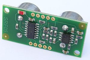
Low Cost Ultrasonic Range Finder
Tutti i prezzi sono IVA inclusa
Introduction
The SRF05 is an evolutionary step from the SRF04, and has been designed to increase flexibility, increase range, and to reduce costs still further. As such, the SRF05 is fully compatible with the SRF04. Range is increased from 3 meters to 4 meters. A new operating mode (tying the mode pin to ground) allows the SRF05 to use a single pin for both trigger and echo, thereby saving valuable pins on your controller. When the mode pin is left unconnected, the SRF05 operates with separate trigger and echo pins, like the SRF04. The SRF05 includes a small delay before the echo pulse to give slower controllers such as the Basic Stamp and Picaxe time to execute their pulse in commands.
Mode 1 - SRF04 compatible - Separate Trigger and Echo
This mode uses separate trigger and echo pins, and is the simplest mode to use. All code examples for the SRF04 will work for the SRF05 in this mode. To use this mode, just leave the mode pin unconnected - the SRF05 has an internal pull up resistor on this pin.


Mode 2 - Single pin for both Trigger and Echo
This mode uses a single pin for both Trigger and Echo signals, and is designed to save valuable pins on embedded controllers. To use this mode, connect the mode pin to the 0v Ground pin. The echo signal will appear on the same pin as the trigger signal. The SRF05 will not raise the echo line until 700uS after the end of the trigger signal. You have that long to turn the trigger pin around and make it an input and to have your pulse measuring code ready. The PULSIN command found on many popular controllers does this automatically.


To use mode 2 with the Basic Stamp BS2, you simply use PULSOUT and PULSIN on the same pin, like this:
SRF05 PIN 15 ' use any pin for both trigger and echo Range VAR Word ' define the 16 bit range variable SRF05 = 0 ' start with pin low PULSOUT SRF05, 5 ' issue 10uS trigger pulse (5 x 2uS) PULSIN SRF05, 1, Range ' measure echo time Range = Range/29 ' convert to cm (divide by 74 for inches) |
Calculating the Distance
The SRF05 Timing diagrams are shown above for each mode. You only need to supply a short 10uS pulse to the trigger input to start the ranging. The SRF05 will send out an 8 cycle burst of ultrasound at 40khz and raise its echo line high (or trigger line in mode 2). It then listens for an echo, and as soon as it detects one it lowers the echo line again. The echo line is therefore a pulse whose width is proportional to the distance to the object. By timing the pulse it is possible to calculate the range in inches/centimeters or anything else. If nothing is detected then the SRF05 will lower its echo line anyway after about 30mS.
The SRF04 provides an echo pulse proportional to distance. If the width of the pulse is measured in uS, then dividing by 58 will give you the distance in cm, or dividing by 148 will give the distance in inches. uS/58=cm or uS/148=inches.
The SRF05 can be triggered as fast as every 50mS, or 20 times each second. You should wait 50ms before the next trigger, even if the SRF05 detects a close object and the echo pulse is shorter. This is to ensure the ultrasonic "beep" has faded away and will not cause a false echo on the next ranging.
The other set of 5 pins
The 5 pins marked "programming pins" are used once only during manufacture to program the Flash memory on the PIC16F630 chip. The PIC16F630's programming pins are also used for other functions on the SRF05, so make sure you don't connect anything to these pins, or you will disrupt the modules operation.
Changing beam pattern and beam width
You can't! This is a question which crops up regularly, however there is no easy way to reduce or change the beam width that I'm aware of. The beam pattern of the SRF05 is conical with the width of the beam being a function of the surface area of the transducers and is fixed. The beam pattern of the transducers used on the SRF05, taken from the manufacturers data sheet, is shown below.

