MD14 - 24Volt 5Amp H Bridge Motor Drive
Tutti i prezzi sono IVA inclusa
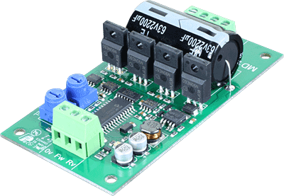
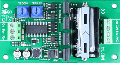
The MD14 is a medium power motor driver, designed to provide the easiest motor control possible to a single motor. Adjustments to speed and acceleration can be made by rotating the potentiometers on the PCB, forward and reverse outputs are controlled by 24v inputs.
Motor connections
|
Inputs for control |
|
Motor supply and output terminals 0v - Motor supply 0v ground M2 - Motor output voltage pole 2 M1 - Motor output voltage pole 1 24v - Motor supply 24vdc |
Circuit protection
There is no fuse on the PCB. You should provide a 5A fuse in line with the +v battery terminal.
Be sure to use cable rated for at least 5A for the Battery, Fuse and Motor leads
Motor Noise Suppression
Please note that using motors with the MD14 as with any other electronic device requires suppression of noise. This is easily achieved by the addition of a 10n snubbing capacitor across the motor. The capacitor should also be capable of handling a voltage of twice the drive voltage to the motor.
Drive inputs
When 5-24v appears on the terminal a green LED indicator will light and the MD14 will drive the motor accordingly, if both inputs are present then the MD14 will not drive the motor. You don't need to wait for the motor to stop to alternate the input direction, the MD14 will slow the motor using the desired deceleration (same rate as acceleration) and then accelerate in the new direction.
Speed adjustment
Rotating the potentiometer marked SPEED clockwise will increase the maximum power output, anticlockwise rotation will reduce the maximum power until the limit of travel is reached and the motor will be stopped.
Acceleration adjustment
Rotating the potentiometer marked ACCEL clockwise will increase the rate at which the power is delivered to the motor. The acceleration rate can be varied from 0.2 to 2 seconds to reach full speed from stop, or to slow down to a stop from full speed.
Over current detection
An automatic regular check of the output current is performed and power is removed if a excessive load is applied, the red error LED will light and indicate:
Red LED is flashing - Output current limit exceeded, reduce load and cycle power to reset.
Red LED is on - A very large current has been detected, this is likely to have been from a short circuit on the motor output, check wiring before cycling power to reset.
PCB Dimensions
The following drawing shows the MD14 mounting hole positions.


