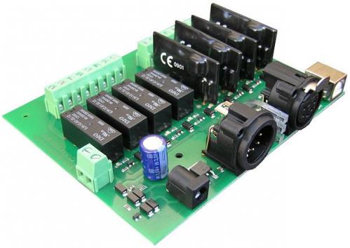
DMX-USB-RX-RLY8 Relay Output Module 4 Relays 4 Dimmer
All prices are VAT included
The DMX-USB-RX-RLY8 module is a fully compliant with the latest USITT DMX512-A standard, E1.11-2004. This small module, powered by a single 9V AC or 12V DC supply, provides 8 Relay outputs. These can be mechanical or solid state relays.
Features
Fully compliant with the latest USITT DMX512-A standard.
Backwards compatible with the older USITT DMX512/1990 standard.
Easy to use configuration via a USB port. PC application supplied, no dip switches to worry about.
Uses a single 9V AC or 12V DC supply for power.
Module can be set to any DMX address from 1-505.
Mechanical Relays up to 250VAC 8Amp.
Solid State Relays for phase controlled Dimming, Up to 250VAC 5Amp.
DMX feed though on all pins, including 4 & 5.
Selectable 120 Ohm termination.
Connections
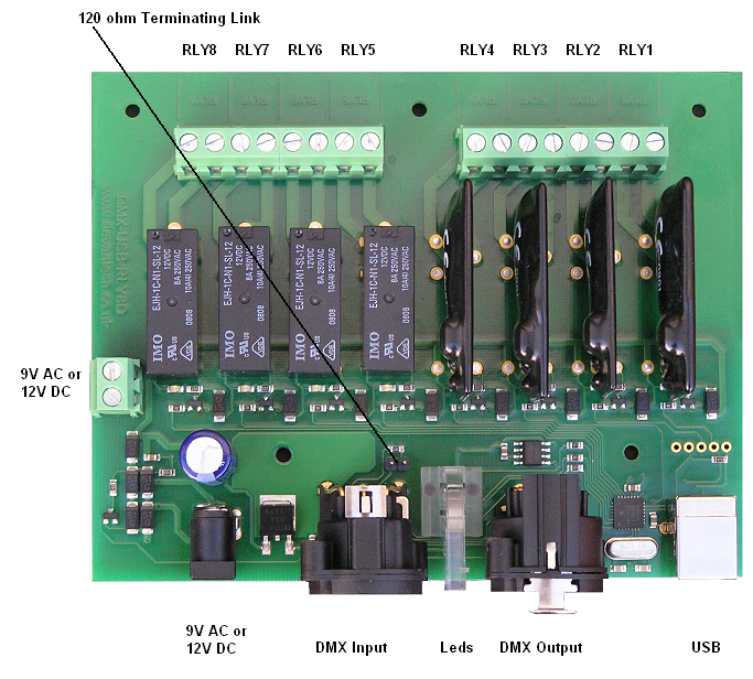
Power can be connected to the module either from a 9v AC transformer to the two pin screw terminals, or from a 9v AC adapter. If you are not using the dimmer relays then you can use 12v DC instead, the module cannot be powered from the USB port. The 120 ohm terminating link connects an on-board 120 ohm resistor across the DMX, this should only be fitted to the last module on the DMX cable. Remove the link on ALL other modules.

Getting Started
The default factory settings for your DMX-USB-RX-RLY8 module is DMX address 1 and all relays set to on/off mode. The threshold level for on/off is 128 with a hysteresis of 3. If the level goes below 127 the relay will turn off (open). If the level goes above 129 the relay will turn on (closed). Levels 127 to 129 do nothing, to protect against any jitter from the faders.
If this is what you need then just connect the 9V AC or 12V DC supply, plug in the DMX cable and your away.
It's more likely that you want to select a different DMX address or to change one or more solid state relays to dimmer mode. To do this you will need a PC running Windows 2k/XP/Vista.
You will need these two files (in the installation file below):
The DMX_RLY8 Configuration program.
The USB driver for windows.
Unzip the DMX_RLY8 Installation file into a temporary folder and click "setup" to install it.
Next install the USB driver. If you are using Vista, temporarily disconnect your computer from the internet by unplugging the network cable or switching off the wireless connection. This is because Vista will go off and look for a suitable driver and not offer you the chance to direct it to the correct driver. It will probably install the wrong driver. Disconnecting the internet first will force it to ask you where to look. XP is fine, it asks you anyway. Connect the 18vac supply to the module, then plug in the USB cable. Windows should detect the new module and ask for the driver. Direct windows to the "inf" file and windows will install the driver. Once installed you will have a new serial communication port listed in Device Manager.
Run the DMX_RLY8 Configuration program, and you will see the following dialog. Select the new comm. port and it will find the module and display its software revision number. The DMX address the module is currently set to is displayed and if the module is receiving DMX, the levels are also visible.

Changing the Relay Mode
To select Dimmer mode for any relay, just check its tick box and click the update button. You should only do this where a solid state relay is fitted to the module. Doing this on normal mechanical relays will just cause them to chatter continuously. To use Dimmer mode you must also supply 9VAC to the module. If you use a DC power supply the module will revert to normal relay mode.
Changing the DMX address
The DMX address can be set to any between 1 and 505. Just enter the new address in the "DMX Address" edit box and click the "Update" button. The 8 channels on the DMX-USB-RX-RLY8 module are numbered consecutively. If you select address 505, then channel RLY1 will be at address 505, channel RLY2 will be at address 506 and channel RLY8 will be at address 512.
DMX Connections
The 5-pin XLR connections follow industry standard pin-out.
| Use | 5-pin XLR Pin number | DMX512 Function |
| Common Reference | 1 | Data Link Common |
| Primary Data Link | 2 | Date 1- |
| 3 | Date 1+ | |
| Secondary Data Link (unused by module, but connected through on XLR's) |
4 | Date 2- |
| 5 | Date 2+ |
Termination
If the module is the last one on the DMX cable, you should ensure the link is fitted on the board. This will enable the 120 ohm terminating resistor.
Where the DMX is feeding through to other modules further down the cable, this link should be removed.
